Kit component
Stress control tube and stress control mastic
Two numbered line items, one edge. Settle insulation type, core count, mm², Umax and indoor or outdoor before either part is specified.
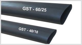
Insultube-Stress heat-shrink stress control tubing
Radiation cross-linked polymeric material, published for insulation-screen terminals and power cable joints up to 36 kV. Standard colour black, and supplied inside kits rather than sold as one.
- Listed as Stress Control Tubing, 3 Nos., in the GXO/E-1112, GXO/E-1524 and GXO/E-3336 bills of material
- Yellow HSCM stress control mastic is a separate numbered line in the same lists
- Alternatives inside the same catalogue: the GVOT integrated sleeve, and the Soloterm integrated varistor coating
| Trade name | Insultube-Stress |
|---|---|
| Material | Radiation cross-linked polymeric material |
| Published application | Insulation-screen terminals and power cable joints up to 36 kV |
| Operating temperature | −40 °C to 100 °C |
| Minimum shrink temperature | 100 °C |
| Fully shrunk at | 130 °C |
| Standard colour | Black |
| Codes legible on the manufacturer's photograph | GST - 60/25 and GST - 40/18 |
What the cut-back leaves behind
Inside a screened cable the field is radial and bounded. The insulation screen holds the outer face of the insulation at earth potential along the whole run.
Terminating strips that screen off the exposed core. The earthed boundary then ends at one hard circumferential edge, and the equipotential lines crowd into the few millimetres either side of it.
Neither part on this page puts the screen back. Both spread what the edge concentrates, so potential falls across a length instead of across a step. The manufacturer carries the tube on its own page as Insultube-Stress.
Both parts are down before anything else goes on
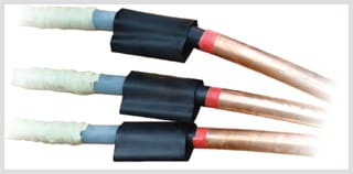
The black tube sits over the step; the red insulating tubing continues past it towards the lug.
Non-tracking tubing, the breakout and any rain sheds are added on top of this. Nothing underneath them is inspectable again.
Geometry or material: which answer is in the box
Geometry. A stress cone flares the earthed boundary outwards and lengthens the surface path from screen to conductor. A tender written around a stress cone termination kit is asking for that construction.
It appears once in this catalogue. The screened separable connector uses one body with stress cone adapters: up to 24 kV they cover 25 to 400 mm², and at 36 kV, 95 to 630 mm². No heat-shrink kit here contains a cone.
Material. A high-permittivity compound laid over the edge redistributes the field and leaves the shape underneath alone. The mastic is where that shows in published figures: yellow HSCM is rated at a dielectric constant of 10 (min.) [ASTM D150], against 2–3 for black HBMT and 3 (max.) for red HRMT. Three grades of one butyl sealant, separated by permittivity.
The tube is compounded for the same job, and no permittivity is published for it. That gap is printed below rather than filled in.
A third arrangement hides the answer inside another part. GVOT is a cross-linked polyolefin sleeve with the stress control system built in; Soloterm carries an integrated varistor coating that bonds to insulation and screen from within, and needs no sheds indoors. Neither leaves the jointer a discrete tube to fit — how each technology grades the field sets the three side by side.
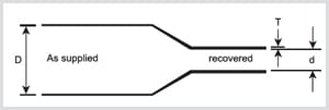
D, d and T, drawn without values
D is the internal diameter as supplied and must clear the largest thing the tube passes over. Letter d is the internal diameter after free recovery and must be smaller than what the tube has to grip. T is the recovered wall.
The manufacturer prints that drawing on the tube's own page and prints no table against it.
Not published — ask the manufacturer
Four things a clause reaches for here, none of them in the manufacturer's published material for this tube, and none estimated on this page. A selection chart — the page draws D, d and T and gives no values; the only two codes anywhere on it are GST - 60/25 and GST - 40/18, read off the product photograph. A permittivity or volume resistivity figure for the compound, which is the whole basis of the material argument, and which is published for the yellow mastic but not for the tube. Any rule relating recovered length to Umax. A mapping from a tube size to a kit code, so a delivered box cannot be checked against a chart on receipt. Ask for the tube's selection chart and its electrical data by kit code through contact.
The mastic goes in before the tube goes on
Stress control mastic is the yellow grade, coded HSCM, and it is not the black sealing tape found elsewhere in the same box. The manufacturer's Mastic Tape datasheet describes it as a stress relief void filling mastic, used on connectors and at screen cuts on medium voltage joints and terminations.
The reason is mechanical before it is electrical. A semi-conducting screen stands proud of the insulation, so cutting it leaves a shoulder. A recovering tube bridges that shoulder rather than flowing into it, and the void left under the bridge sits exactly at the field peak.
All three grades are cold-applied butyl sealant. Nothing on this part shrinks, and no heat is taken to it.
Three mastic grades against one property list
| Property | Yellow HSCM | Black HBMT | Red HRMT | Standard |
|---|---|---|---|---|
| Dielectric constant | 10 (min.) | 2–3 | 3 (max.) | ASTM D150 |
| Dielectric strength | 15 kV/mm (min.) | 6 kV/mm (min.) | 10 kV/mm (min.) | ASTM D149 |
| Volume resistivity | 1 × 10⁹ Ohm·cm (min.) | 1 × 10¹⁰ Ohm·cm (min.) | 1 × 10¹⁴ Ohm·cm (min.) | ASTM D257 |
| Tensile strength | 0.1 MPa (min.) | 0.1 MPa (min.) | 0.5 MPa (min.) | ASTM D638 |
| Ultimate elongation | 300 % (min.) | 300 % (min.) | 300 % (min.) | ASTM D638 |
| Density | 1.30 ± 0.2 g/cm³ | 1.30 ± 0.2 g/cm³ | 1.20 ± 0.2 g/cm³ | ASTM D792 |
| Service temperature | −20 °C to +90 °C | −20 °C to +90 °C | −20 °C to +90 °C | IEC 216 |
| 50 Hz loss factor | 0.035 | 0.035 | 0.035 | — |
From the manufacturer's Mastic Tape datasheet. One row separates the grades: dielectric constant runs 10 (min.) on yellow against 2–3 on black. A screen step filled with the black grade is filled and still ungraded.
Yellow HSCM, as charted
| Code | W (min.) mm | L (min.) mm | T ±5% mm | Form |
|---|---|---|---|---|
| HSCM - 06 | 20 | 100 | 1.7 | Strips |
| HSCM - 09 | 25 | 450 | 1.7 | Strips |
W and L are minimums; T carries ±5%. Both HSCM entries in the chart are strips — the black and red grades also appear as rolls, the yellow grade does not.
This order is reconstructed, and the manual in the box governs
No installation sequence for these two parts is published. The four operations below are reconstructed on this page from the kits' own bills of material and from what each part is described as doing. Every kit ships an installation instruction manual, every dimension belongs to it, and where it differs from this page it governs.
The order the two parts go on in
Cut the insulation screen back
The distance comes from the instruction manual packed with the kit. It is the one dimension on the prepared core the installer does not choose.
Work HSCM into the screen step
Fill the shoulder until nothing is left behind it. Published contents lists carry the mastic as a numbered item of its own, separate from the sealing tape used at the lug.
Recover the tube over the filled step
Minimum shrink temperature is 100 °C and the tube is published as fully shrunk at 130 °C. GXO/E kits carry temperature-sensitive paint that changes colour once shrinking is complete.
Build the insulating and weather layers on top
Non-tracking weather-resistant tubing, breakout and rain sheds follow, and they answer surface tracking rather than field grading. The installation sequence covers the whole assembly.
Two temperatures, two jobs — quote both
Recovery starts at 100 °C and is published as complete at 130 °C. The operating range for the finished part tops out at 100 °C as well, so the same number is both the floor for the gun and the ceiling in service. A clause carrying one temperature for this component is carrying half of it.
Four ways the grading is lost while the termination still looks right
Each of these passes a visual inspection and a tail-length check.
- A cut-back distance taken from the wrong kit. The graded length shortens and the finished core looks identical.
- Mastic skipped or under-filled at the semi-con step. The void that survives sits at the field peak, and it cannot be seen once the tube is down.
- A tube heated to grip rather than to recover. Short of full recovery the wall spans the shoulder instead of following it, so the void simply moves underneath.
- Screen residue, or a solvent film, left on the insulation surface. GPO/E kits list cleaning solvent, 1 bottle, and an emery sheet, 1 No., among the installation aids; GXO/E kits list aloxite emery tape, 3 Nos., with cleaning tissue.
Sources disagree — GVOT at 24 kV, or at 36 kV
The integrated stress control sleeve is published at two ceilings. The manufacturer's component index lists GVOT as an integral part of terminations up to 24 kV. The GVOT datasheet describes the same sleeve as normally used as an integral part of Gala cable terminations for voltages upto 36 kV, and charts six sizes from GVOT 30/12 to GVOT 85/32 at recovered walls of 2.5 to 3.0 mm. Neither document is withdrawn. Confirm which one your order was quoted against before either figure reaches a specification.
Sources disagree — 36 kV or 66 kV for the same compound
The Insultube-Stress page rates the tube for insulation-screen terminals and cable joints up to 36 kV. The component index on the same site rates stress control tube, non-tracking tube and red insulation tube to 66 kV. Both are current and neither is withdrawn, so both are printed here. What is not in dispute: the highest termination kits catalogued anywhere are GXO/E-3336 and GPO/E-3336, and a rating attached to a compound has never been a rating on an assembly. Where the 66 kV figure comes from, and what it is not.
Which kits carry which of the two parts
Neither part is ordered on its own. Both arrive as numbered lines in a kit's bill of materials.
- GXO/E-1112, GXO/E-1524, GXO/E-3336 and GXOS/E-1236 — XLPE and EPRThe three-core lists carry stress control tubing, 3 Nos., against mastic, 3 Nos. Single-core GXOS/E-1236 carries a stress control sleeve, 1 No., with mastic, 1 strip.
- GPO/E-1112, GPO/E-1524, GPO/E-3336 — PILCA stress control sleeve, 3 Nos., at 12 kV; stress control tubing, 3 Nos., plus mastic, 3 strips, at 24 and 36 kV. The 12 kV list is the only MV termination here with no mastic line printed against it.
- GLT-1100 — 1.1 and 3.3 kV, the kit that carries neitherNo stress control item of any kind appears in its published contents, across the 1, 2, 3, 3½ and 4-core constructions it covers.
- GXS/1236 and GXSS-1236 joints carry both, and mastic twiceGXSS-1236 lists stress control mastic for the ferrule region — 2 Nos. at 12 and 24 kV, 4 Nos. at 36 kV — and stress control mastic again as its own line. GXS/1236 prints that second line as grey/yellow.
- How many sheds go on after itThe next decision on an outdoor core, made on creepage rather than on field grading.
- Specifying the kit as a wholeWhere the five inputs at the top of this page become a kit code.
What comes up in specification review
A stress cone and a stress control tube — one part or two?
Can the mastic be left out if the tube overlaps far enough?
Which size of tube arrives in a given kit?
The compound is published at 66 kV. Is that a 66 kV termination?
How do stress control mastic and mastic sealing tape differ on a bill of materials?
Checking a kit list against a real cable?
Send insulation type, core count, mm², Umax and indoor or outdoor, and a published contents list can be checked against them line by line.